Lab 3: Add a Shell and Winc1500 to your project
Purpose
In this lab, the student will enable the Zephyr shell over UART, inspect running threads with built-in shell commands, name threads for easier debugging, add a Device Tree overlay to expose the ATWINC1500 Wi-Fi module over SPI, and use the network shell to scan for and connect to a Wi-Fi access point.
Overview
Lab 3 builds on the two-thread project from Lab 2. First you will enable the Zephyr shell and explore the system at runtime. Next you will write a Device Tree overlay that wires the ATWINC1500-XPRO extension board to the SAM E54 Xplained Pro's SPI peripheral. Finally you will add the necessary Kconfig options and use the network shell to bring up a Wi-Fi connection.
Procedure
Step 3.1: Enable and Explore the Zephyr Shell
3.1.1: Open prj.conf and add the following line to enable the Zephyr shell subsystem:
CONFIG_SHELL=y
3.1.2: Open src/producer.c and src/consumer.c and remove the printk calls in the thread functions so the shell prompt is not obscured by continuous output:
In producer.c:
        if(counter++>=10) {
            printk("(producer) Putting %d into message queue\n", data);
            k_msgq_put(notifyMsgQueue, &data, K_NO_WAIT);
            data++;
            counter = 0;
        }
In consumer.c:
    while (1) {
        k_msgq_get(notifyMsgQueue, &data, K_FOREVER);
        printk("(consumer) Received data: %d\n", data);
    }
3.1.3: Build and flash the updated firmware:
- Ubuntu
- macOS
- Windows
(.venv) $ west build -p always -b same54_xpro application
(.venv) $ west flash
(.venv) $ west build -p always -b same54_xpro application
(.venv) $ west flash
(.venv) PS C:\...\zephyrproject> west build -p always -b same54_xpro application
(.venv) PS C:\...\zephyrproject> west flash
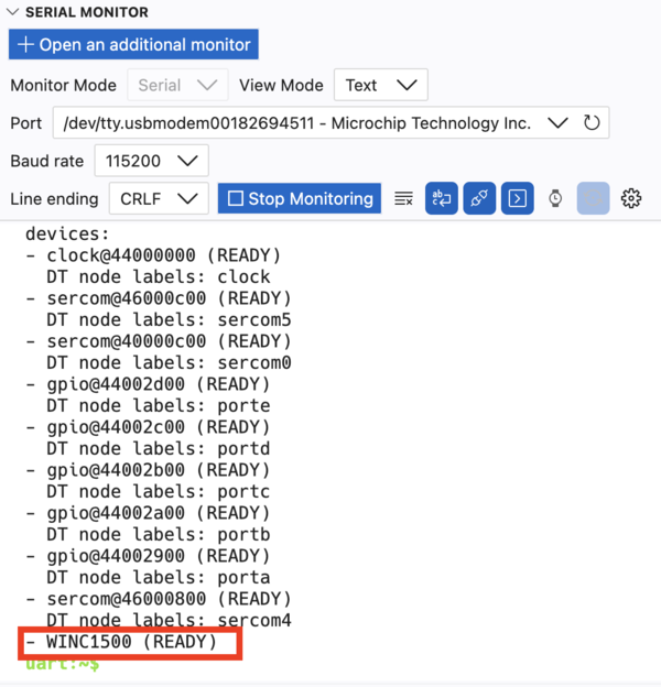
3.1.4: Open the Serial Monitor. To use the interactive shell you must configure line endings to CRLF (both send and receive). Set this option in the Serial Monitor settings panel before connecting.

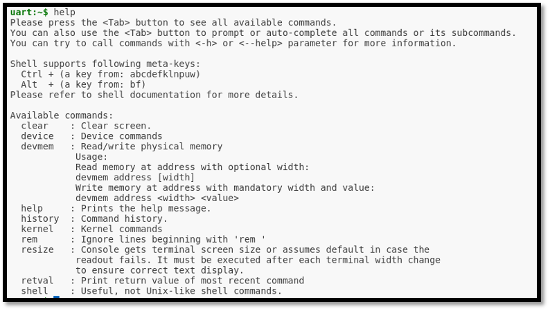
Once connected you should see the uart:~$ prompt. Type help to list all registered shell
modules and their top-level commands:
uart:~$ help
3.1.5: List all registered Zephyr devices by typing the following command at the shell prompt:
uart:~$ device list
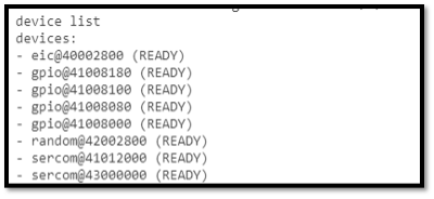
Observe the output - every driver that was compiled into the image and successfully initialised will appear here.
3.1.6: List all active Zephyr threads and their current state, priority, and stack usage:
uart:~$ kernel thread list
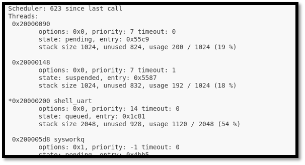
Notice that the producer and consumer threads appear with auto-generated numeric names. The next step will make them easier to identify.
3.1.7: Open main.c and add the following two calls immediately after the k_thread_create calls for the producer and consumer threads:
	k_tid_t producer_tid = k_thread_create(&producerThread_data,
                         producerThreadstack_area,
                         K_THREAD_STACK_SIZEOF(producerThreadstack_area),
                         producerThread,
                         (void*)&led, (void*)&consumerQueue, (void*)NULL,
                         PRIORITY, 0, K_NO_WAIT);

	k_tid_t consumer_tid = k_thread_create(&consumerThread_data,
                          consumerThreadstack_area,
                          K_THREAD_STACK_SIZEOF(consumerThreadstack_area),
                          consumerThread,
                          (void*)NULL, (void*)&consumerQueue, (void*)NULL,
                          PRIORITY, 0, K_NO_WAIT);

	k_thread_name_set(producer_tid, (const char *)"producer");
	k_thread_name_set(consumer_tid, (const char *)"consumer");

	while (1) {
		k_msleep(SLEEP_TIME_MS);
	}
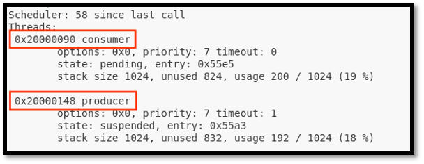
3.1.8: Rebuild, flash, and rerun kernel thread list in the shell. The producer and consumer threads should now appear with their human-readable names.
uart:~$ kernel thread list
3.1.9: CHALLENGE - Stack Usage Analysis
While looking at the kernel thread list output, examine the unused stack column for your
producer and consumer threads. The STACKSIZE macro in main.c is currently set to 1024 bytes
for both threads.
Consider: is 1024 bytes the right size? If the unused stack is very large you are wasting RAM.
If it is very small the thread is at risk of a stack overflow. Try reducing STACKSIZE for
one or both threads and observe whether the firmware still builds and runs correctly. What is
the minimum safe stack size for each thread?
Step 3.2: Add a Device Tree Overlay for the ATWINC1500
The ATWINC1500-XPRO extension board connects to the SAME54 Xplained Pro via one of its EXT headers. The table below shows the relevant signal mappings for the EXT1 connector (the default used in this lab). An EXT3 alternative is provided in the collapsible section after the overlay listing.
| WINC1500 Signal | XPRO Pin | SAME54 Xplained Pro Port/Pin |
|---|---|---|
| RESET | 5 | PA6 |
| WAKE | 6 | PA7 |
| IRQ | 9 | PB7 |
| CHIP ENABLE | 10 | PA27 |
| SPI CS | 15 | PB28 |
3.2.2: Create a boards/ directory inside your application directory and create the overlay file:
- Ubuntu
- macOS
- Windows
(.venv) $ mkdir -p application/boards
(.venv) $ touch application/boards/same54_xpro.overlay
(.venv) $ mkdir -p application/boards
(.venv) $ touch application/boards/same54_xpro.overlay
(.venv) PS C:\...\zephyrproject> mkdir application\boards
(.venv) PS C:\...\zephyrproject> ni application\boards\same54_xpro.overlay
3.2.3: Open application/boards/same54_xpro.overlay and add the following Device Tree content to switch SERCOM4 to the XPRO header pins and attach the WINC1500 as a device on that bus:
&sercom4 {
    pinctrl-0 = <&sercom4_spi_xpro>;
    cs-gpios = <&portb 28 GPIO_ACTIVE_LOW>;

    sercom4_cs0_winc1500: WINC1500@0 {
        compatible = "atmel,winc1500";
        reg = <0>;
        spi-max-frequency = <12000000>;
        irq-gpios    = <&portb 7  GPIO_ACTIVE_LOW>;
        reset-gpios  = <&porta 6 GPIO_ACTIVE_LOW>;
        enable-gpios = <&porta 7  GPIO_ACTIVE_HIGH>,
                       <&porta 27  GPIO_ACTIVE_HIGH>;
        status = "okay";
    };
};
enable-gpios lists two pins, comma separated. Since the CHIP_EN pin and the WAKE pin largely share functionality for our demo, listing them both allows the software driver to toggle them together when the chip is enabled or disabled. You could also use a Devicetree GPIO node to configure the WAKE pin separately to manage it on your own.
Alternative: EXT3 overlay (SERCOM6)
If your ATWINC1500-XPRO is connected to the EXT3 header instead of EXT1, use the following
overlay content instead. EXT3 uses SERCOM6 with Port C pins and requires an additional
pinctrl node because the default sercom6_spi_default pinmux is not defined in the board
files.
EXT3 Pin Mapping
| WINC1500 Signal | EXT3 Pin | SAME54 Xplained Pro Port/Pin |
|---|---|---|
| SPI CS | 15 | PC14 |
| SPI MOSI | 16 | (pinctrl) |
| SPI MISO | 17 | (pinctrl) |
| SPI SCK | 18 | (pinctrl) |
| IRQ | 9 | PC30 |
| RESET | 10 | PC1 |
| ENABLE (CHIP EN) | 11 | PC10 |
| ENABLE (VCC EN) | 12 | PC31 |
/
{
    aliases {
    };
};

&gmac {
    status = "disabled";
};

&pinctrl {
    sercom6_spi_overlay: sercom6_spi_overlay {
        group1 {
            pinmux = <PC5C_SERCOM6_PAD1>,
                     <PC4C_SERCOM6_PAD0>,
                     <PC7C_SERCOM6_PAD3>;
        };
    };
};

&sercom6 {
    compatible = "atmel,sam0-spi";
    dipo = <3>;
    dopo = <0>;
    #address-cells = <1>;
    #size-cells = <0>;
    cs-gpios = <&portc 14 GPIO_ACTIVE_LOW>;
    pinctrl-0 = <&sercom6_spi_overlay>;
    pinctrl-names = "default";
    status = "okay";

    sercom6_cs0_winc1500: WINC1500@0 {
        compatible = "atmel,winc1500";
        reg = <0>;
        spi-max-frequency = <12000000>;
        irq-gpios    = <&portc 30 GPIO_ACTIVE_LOW>;
        reset-gpios  = <&portc 1  GPIO_ACTIVE_LOW>;
        enable-gpios = <&portc 10 GPIO_ACTIVE_HIGH>,
                       <&portc 31 GPIO_ACTIVE_HIGH>;
        status = "okay";
    };
};
3.2.4: Open prj.conf and append the following Kconfig options to enable Wi-Fi, the WINC1500 driver, and the networking stack:
CONFIG_WIFI=y

CONFIG_WIFI_WINC1500=y
CONFIG_NETWORKING=y
CONFIG_NET_IPV4=y
CONFIG_TEST_RANDOM_GENERATOR=y

CONFIG_NET_PKT_RX_COUNT=16
CONFIG_NET_PKT_TX_COUNT=16
CONFIG_NET_BUF_RX_COUNT=32
CONFIG_NET_BUF_TX_COUNT=16
CONFIG_NET_MAX_CONTEXTS=16

CONFIG_NET_DHCPV4=n
CONFIG_DNS_RESOLVER=n

CONFIG_NET_TX_STACK_SIZE=2048
CONFIG_NET_RX_STACK_SIZE=2048

CONFIG_NET_SHELL=y
CONFIG_NET_L2_WIFI_SHELL=y
3.2.5: Perform a pristine build to ensure the overlay and new Kconfig options are picked up cleanly:
- Ubuntu
- macOS
- Windows
(.venv) $ west build -p always -b same54_xpro application
(.venv) $ west build -p always -b same54_xpro application
(.venv) PS C:\...\zephyrproject> west build -p always -b same54_xpro application
- Ubuntu
- macOS
- Windows
(.venv) $ west flash
(.venv) $ west flash
(.venv) PS C:\...\zephyrproject> west flash
After flashing, open the Serial Monitor and run device list again. The WINC1500 should now
appear as an initialised device:
uart:~$ device list
Step 3.3: Scan for and Connect to a Wi-Fi Network
With the WINC1500 driver active and the network shell enabled, you can control Wi-Fi directly from the Zephyr shell over the Serial Monitor.
3.3.1: Trigger a Wi-Fi scan to discover nearby access points:
uart:~$ wifi scan
Wait a few seconds for the scan to complete. A table of discovered SSIDs, signal strengths, channels, and security modes will be printed to the console.

3.3.2: Connect to RTOS1 wifi network using the passphrase zephyr4microchip.
uart:~$ wifi connect -s RTOS1 -p zephyr4microchip -k 1
The -k 1 flag selects WPA2-PSK security. The shell will print a connection status event when
the association completes.
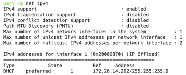
3.3.3: Verify that the network interface has been assigned an IPv4 address:
uart:~$ net ipv4
3.3.4: Inspect the network interface to confirm the Wi-Fi link is up:
uart:~$ net iface
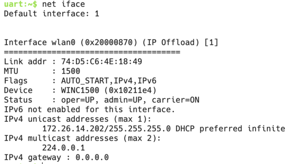
The gateway IP displays as 0.0.0.0 because the full IP stack, including routing and gateway assignment, is offloaded to the WINC1500 module, so Zephyr's network interface is never populated with the gateway address.
3.3.5: Send a UDP packet to a listening host using the network shell:
uart:~$ net udp send 172.26.14.102 56335 "Hello from YourName"
You should now see your name on the UDP listener on the screen!
Even if your name appears on the presentation screen, the UART shell will still report that the UDP send failed. The packet was actually transmitted successfully, but the WINC1500 send complete callback is not implemented, so Zephyr is never notified of the successful send.
Results
You have enabled the Zephyr shell, inspected thread state at runtime, attached the ATWINC1500 Wi-Fi module through a Device Tree overlay, and used the network shell to scan for, connect to, and send data over a Wi-Fi access point - all without modifying the Zephyr kernel source.
Summary
This lab covered three important Zephyr concepts:
- The shell subsystem (
CONFIG_SHELL=y) provides a powerful runtime introspection and control interface over any serial backend. Thekernel threadscommand shows live thread state and stack usage;device listconfirms which drivers initialised successfully. - Device Tree overlays allow you to describe board-level hardware connections (such as
an SPI-attached Wi-Fi module) without modifying the upstream board definition files. The
cs-gpios,irq-gpios,reset-gpios, andenable-gpiosproperties map physical header pins directly into the driver. - The networking stack and Wi-Fi shell (
CONFIG_NETWORKING,CONFIG_NET_L2_WIFI_SHELL) give you a high-level API for bringing up wireless connectivity with minimal application code. Commands likewifi scan,wifi connect,net ipv4, andnet udp sendlet you test the full network path interactively from the shell.